
Using Robot Operating System (ROS 2) in anti-drone, dual-use applications
- Apr 9
- 4 min read
Modern warfare has entered an era of cost asymmetry, where hobbyist-grade drones costing as little as $500 are effectively neutralizing multi-million dollar military assets. This shift is redefining the economics of conflict, forcing global superpowers to rethink traditional defense strategies centered on "exquisite" high-end platforms. The traditional warfare is over.
The primary driver of this revolution is the massive price gap between drones and the targets they destroy or the missiles required to intercept them.
Lethal ROI: Ukrainian forces have used $500 FPV (First-Person View) drones to disable $1.2 billion S-400 air defense systems.
Asset Displacement: The U.S. Army recently withdrew M1A1 Abrams tanks from frontlines due to their extreme vulnerability to $500–$1,500 drones.
The Interception Gap: Conventional air defense is becoming economically unsustainable; it currently costs roughly $1 million or more to intercept a single $20,000–$35,000 Shahed drone using systems like the Patriot.
We are now in a Drone-on-Drone Warfare: To fix the cost imbalance, nations are developing $5,000–$20,000 "interceptor drones" to take down other UAVs, replacing $200,000+ missiles. In many cases civilian-grade equipment is adapted to dual-use equipment in the anti-drone solutions.
Below we describe one project, where we leveraged inexpensive hardware and publicly available open-source software frameworks to build dual-use, anti-drone solution using ROS 2.
Physical setup
We used the following hardware:
CubePilot Cube Orange flight controller
Arducam RGB camera
The hardest part is choosing the camera. With a wide FOV, the target is visible even when it makes sudden movements, but it appears smaller in the image, making it harder to detect. With a narrow FOV, the target appears larger in the image, but even small movements cause it to move out of the frame.
The Jetson communicates with the Cube Orange using the MAVLink protocol, with both devices connected via USB. In PX4, there is an Offboard mode designed for controlling the autopilot with an external computer, enabling autonomous flight.

System architecture with ROS
The classic monolithic style—where objects are passed between classes and values are often returned via callbacks—is not the best fit for systems at the proof-of-concept stage.
It assumes a well-defined architecture from the very beginning, which conflicts with the highly dynamic nature of such environments and can slow down the development.
ROS (Robotic Operating System) solve the following problems. The biggest advantage of using ROS is that it provides a ready-made system for inter-process communication via topics, services, or actions. It also has a large community and debugging tools like Foxglove, which can help you track topic values.

In this diagram, each square represents a separate process that communicates with others through topics and a set of messages.
It is worth noting that ROS supports zero-copy communication, which is very important in image processing. This helps reduce detection latency as well as video stream latency.
Simulation
Before conducting real-world flights, we first test our solutions in a simulator called Gazebo. This simulator offers excellent support for the PX4 autopilot. You can also easily create your own scenarios or plane models equipped with the sensors and cameras you need.
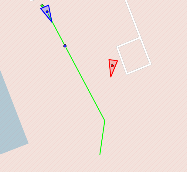
For our purposes, I’m using two aircrafts: one is our target, and the other is the plane we want to use to hit the target. Our plane also has a camera mounted on its nose.

Enemy drone capture - how anti-drone system works
First stage
Before using the detection model, we first need to approach the target. To achieve this, we generate a dynamic path that guides the aircraft toward the target.
The ground-based radar transmits information about the target's location to our system. Using predictive path planning and pure pursuit, we reach the target.
Once we determine that we are behind the target, we activate the detection model to ensure we are tracking the correct object and not following unintended targets. The model is trained to detect different types of UAVs.
Second stage
The YOLO node is activated. This node uses the YOLO v26n model to detect objects in the image. The detection results are sent to the target tracker module, which processes them and forwards them to the visual guidance system node along with an error value used by the PID controller.
A PID controller, which relies on the position of the target in the image, generates control signals for yaw and pitch. This keeps the target in a specific location within the image.
The PID controller's output data is sent to MAVROS—a ROS node used to communicate with PX4 via the Mavlink protocol.

Based on the image, we control only the roll and pitch. However, we also need to adjust the throttle to maintain a specific distance from the target. To do this, we use radar data and a PID controller.
Third stage
The hit phase occurs after the target is locked. Target acquisition means that the target remained in a specific location on the display for a certain period of time, within certain boundaries.
The target-hitting procedure does not simply involve increasing the thrust to 100%. We still want to use a PID controller to control the speed. This is because we want to maintain a specific speed relative to the target speed. Therefore, we do not reach the target value at the maximum possible speed. The greater the speed difference, the harder it is to reach the target value.

Summary - modern dual-use applications
The first test flights have shown that the concept works. We were able to approach the target and follow it based on the image. This makes it possible for us to develop a low-cost anti-drone defense system. More flights need to be conducted under various scenarios and weather conditions.

This is how we work with dual-use technologies in UAVs at Apptimia. If you're building your own anti-drone system or simply need ROS 2 experts and want to leverage our capabilities and our 10 year UAV software experience, get in touch with us!
Maciej K., Senior Software Engineer at Apptimia


